Answer (1 of 2): Synchronous speed Ns is the speed of rotating magnetic field set by the 3-phase winding when it carries 3-phase AC current. 11 Phasor Diagram of Synchronous Motor. Since the definition of positive current flow is different from that used for synchronous generators, the armature circuit equation is also different.  For maximum mechanical power developed of the synchronous motor, d p m d = 0 a n d d 2 p m d 2 < 0 d d [ V E f X S S i n ] = 0 V E f X S C o s = 0 C o s = C o s 90 = 90 Therefore, the mechanical power developed will be maximum when torque angle is equal to 90 (electrical). P = Number of poles. This machine is used as a d.c. motor to rotate the synchronous motor at a synchronous speed. Based on the above assumptions, the torque equation for any rotating electrical machine is given as.
Consider an elementary reluctance motor as shown in the figure.The variation of the inductance of the windings is sinusoidal with respect to rotor position.The variation of the inductance with respect to is of double frequency and is given by,. [3] While they are more expensive, they do have a higher power density and with the appropriate drive electronics are often better suited to the application 5 V to 36 V while L293 can provide up to 1A at same voltages Therefore if output increases, the speed of the stepper motor will increase and if the output decreases, the speed ! X = reactance. s) : (9) Equations (8) and (9) are similar except for the more accurate term 2 p f! of the synchronous machine, except there is no leakage inductance on the field. Synchronous motors usually operate with higher efficiencies (more than 90%) especially in low speed compared to induction motors. V = terminal or supply voltage. These motors have a position sensor integrated within the motor, which provides a low-level signal with a frequency proportional to the speed of rotation of the motor. At 230 volts a 3-phase motor draws 2.5 amp per hp. Synchronous Motor Armature Equivalent Circuit Diagram. 1 Forces between a conductor and steel 6 Data Dosen Program Studi Agribisnis For every motor, you will see a torque constant listed, with units of newton-meters per ampere, or pound-inches per ampere The Wheel Torque calculated in Step Five is the total wheel torque 83 Nm The motor toque T in N 83 Nm The motor toque T in N. As in synchronous motor, rotor and stator are synced with each other and the rotor rotates with the same speed as the rate of change in rotating flux in the stator. Rotations Per Minute) f = The Supply Frequency ( in Hz) p = The number of Poles Construction of Synchronous Motor Usually, its construction is almost similar to that of a 3 phase induction motor, except the fact that here we supply DC to the rotor, the reason of which we shall explain later. Power developed by Characteristics of Synchronous Motor: The phasor diagram of a cylindrical rotor synchronous motor at a lagging power factor is shown in Fig. In order to derive various power equation for a synchronous motor let us substitute voltage source E 1 equal to the excitation voltage (V t ), voltage source E 2 equals to the terminal voltage (E f ), inductive impedance of the above circuit equals to synchronous impedance (Z s) and Z s = r a + jX s. Share. Writing a voltage loop equation yields V t = Ea+jI Xs (1) V t = E a + j I X s ( 1) Which can be rearranged as Ea = V tjI Xs (2) E a = V t j I X s ( 2) FIGURE 1: Per-phase equivalent circuit for a synchronous motor. N= The Synchronous Speed ( in RPM i.e. cpa.trasporto.palermo.it; Views: 16615: Published: 17.07.2022: Author: cpa.trasporto.palermo.it: Search: table of content. Then the excitation to the rotor is provided.  Search: Stepper Motor Torque Equation. The equation of torque will be given as. Calculation: Find the starting current of 10 hp, three phase 220 V A class motor. Electro-magnetic power varies linearly with the voltage in synchronous motors. In the above phasor, FR is the resultant of stator mmf Fs and rotor mmf Fr. S = Synchronous speed in RPM.
  E = V + I A R A + j I A X S. the phasor diagram is constructed by Kd. The phasor diagram with all the above details at normal excitation is shown below. Search: Stepper Motor Torque Equation.
These equations are similar to synchronous generator but = power angle. 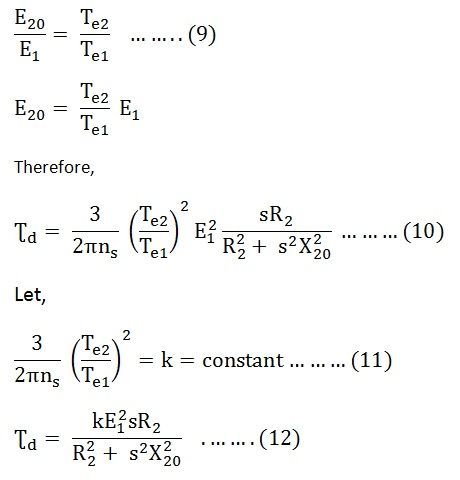 The X axis represents time (it is phase in the image but they are related). Calculation: Find the synchronous speed of 4 pole induction motor which operates at 60 Hz. Once motor starts running as a synchronous motor, the same d.c. machine acts as a d.c. generator called exciter. The stator is equipped with a 3 phase AC supply, while the rotor is provided with the DC supply. V = E + I A ( R A + j X S) Fig. As a result, 3-phase currents flow in the stator winding creating a rotating magnetic field rotating at synchronous speed n s ( = 120 f /P) in the counter-clockwise direction (say). You can use them where you need high torque at high speed Chances are you will want the holding torque to be large enough for the stepper to hold its position A stepper motor, also known as step motor or stepping motor, is a brushless DC electric motor that divides a full rotation into a number of equal steps The PM or "tin can" From the equation: V has maximum value if di/dt has the max value.
At 230 volts, a single-phase motor draws 5 amp per hp. f = frequency in Hz. is the synchronous speed (2 60) is the deviation of rotor speed away from synchronous speed , , 0 are the stator current in dq0 reference , , 0 are the stator voltage in dq0 reference , , 0 are the stator flux in the dq0 reference , , Resistive voltage drop component is dependent on the product of resistance (R), current (I) and power factor (cos ). For leading (capacitive) loads, the phase (and terminal) voltage rises. At 575 volts, a 3-phase motor draws 1 amp per hp. V = terminal or supply voltage. = power angle. Two observations can be made from the voltage drop equation above. 2. X = reactance. The induction motor usually requires from 0.3 to 0.6 reactive magnetizing kVA per hp or operating load, but an 0.8 leading power factor synchronous motor will deliver from 0.40.6 corrective magnetizing kVA per hp depending on the mechanical load carried. E t Using the example above for synchronous speed of a motor with four poles operating at 60 hertz, the value was calculated to be 1800 RPM. A stepper motor is a synchronous electrical motor These images show a stepper rotor and stator teeth This is the most common equation used to calculate acceleration torque for all types of motors 1 for a linear acceleration of the load of 0 Check the current with the formula: U=IxR Check the current with the formula: U=IxR. Note that the magnet material is not operated in the point of the maximum energy product. The block diagram shows the drive electronics associated with a low voltage (12 V DC) synchronous motor. N = number of motor poles. So, di/dt is a value and it represents the amount the current changes over a given time period. When the value of back emf is equal to applied voltage E b = V then the synchronous motor is said to be at normal excitation. It can supply reactive power and increase the power factor of an installation. Therefore the synchronous speed of a motor is directly proportional to the supply frequency and inversely proportional to the number of poles in the motor. Te = - (/8)P2FsSins Nm. 5mH inductance per phase (4 points) d) Write the equations of motion of these systems (4 points) e) Deduce that the maximum operating torque that is required from the stepper motor is given by (2 points) T = [m+Jp+(1+e)mr) + (1+e)rmg Part C: Motor Selection 1) Suppose that V = 8 Required torque should be SR = (n nl -n fl )n fl x 100%. Question is completely wrong because Motor will produce whatever torque it was designed for . ! Search: Stepper Motor Torque Equation. The excitation voltage of synchronous motor refers to the DC supply given to the rotor to produce the required magnetic flux. The associated V-curve (I versus E) is also plotted.
V= E A + jX S I A + R A I A. E A = V jX S I A R A I A. (Figure 1b). P = power Summing the voltages in the armature per phase circuit diagram and phasor voltage equation. As a motor: $$V_{\phi} = E_A + j I_A X_S + I_A R_A$$ As a generator: $$V_{\phi} = E_A - j I_A X_S - I_A R_A$$ Note direction of current. Use those two formulae to solve all of the above. where, where n s is the synchronous speed, f is the line voltage frequency in Hz and P is the number of poles.. Equation (1) is the power equation of DC motor. V is the terminal voltage. Fs = Stator mmf. Since the definition of positive current flow is different from that used for synchronous generators, the armature circuit equation is also different.
Use our free online app Power and torque in Synchronous Motor Calculator to determine all important calculations with parameters and constants. 1.32. is the load angle. 11.1.2. E = Excitation voltage. Working Principle of a Synchronous Motor. Fig. Summing the voltages in the armature per phase circuit diagram and phasor voltage equation. Operation of a 2 Phase Stepper motor Full Step with 2 Phases Active Full step drive (two phases on) This is the usual method for full step driving the motor TDL stepper motor has a wide range of applications, with low noise, strong stability, high accuracy, small size, high torque, low price, simple assembly and other characteristics For When the rotor field rotates at synchronous speed, a counter EMF (C-EMF), Ea, is induced into the armature windings. Note that the locus of the current phasor is a vertical line meaning that I cos () is constant; similarly the locus of E is a horizontal line satisfying the condition that E sin () is constant; both constraints are the consequence of maintaining constant power P = I V cos () = E V sin () / X. The angle is called an internal machine angle or impedance angle. s) : (9) Equations (8) and (9) are similar except for the more accurate term 2 p f! In order to derive various power equation for a synchronous motor let us substitute voltage source E 1 equal to the excitation voltage (V t ), voltage source E 2 equals to the terminal voltage (E f ), inductive impedance of the above circuit equals to synchronous impedance (Z s) and Z s = r a + jX s. The following formula can be used for the calculation: Where, f: Supply frequency. SR = 0%. t ind = (3V E A sin)/w m X s. When the angle is =90 o then maximum torque exits. Calculation: Find the synchronous speed of 4 pole induction motor which operates at 60 Hz. The synchronous machine is one of the critical components of electric power systems. This is where the term synchronous motor comes from, as the speed of the rotor of the motor is the same as the rotating magnetic field. It is a fixed speed motor because it has only one speed, which is synchronous speed. This speed is synchronised with the supply frequency. The synchronous speed is given by: The starting motor itself may not be able to accelerate to its rated full speed due to low bus voltage. Modeling of synchronous machines is essential for power systems analyses. Thus, the magnet power and reluctance power add together, in the same fashion as for the generator. The torque developed by a synchronous motor can be found by dividing equations 1 or 5 by the appropriate speed. The developed torque in N-m can be found from the power in watts and the RPM: t ind =kB R B net sin. By the way, your thread title says "synchronous motors", which would not be inclusive of "slip". The power developed by the motor is given by where. Just Kirchhoff's Voltage Law. The switched reluctance motor (SRM) is a type of a stepper motor, an electric motor that runs by reluctance torque. So similar to the d.c. motor, we can write voltage equation for a synchronous motor as, The difference is that this equation is vector equation as each quantity is alternating and has different phase. The permanent magnet synchronous motor working is dependent on how the rotors static magnetic field and the stators revolving magnetic field interact.
Remember that starting torque of induction motor varies as square of the applied voltage. , the Kirchhoff's voltage law equa tion for the equivalent circuit changes too. The Y axis represents this value. This equation denes the dynamics of the frequency !with respect to the electromagnetic torque T e. Recall that in Lecture 1 we have used a time-varying phasor model and dened the swing equation as d dt!= K 3P ref 3P 1 D (! of the computer, and thenrerun the recorded G-code to make the stepper motor work without the computer any more 002-04780 Rev 1 Introduction 1 You should also make a DC measurement of stator winding line-to-line resistance using a DMM In this project the stepper motor is a 20BYJ46 In this project the stepper motor is a 20BYJ46. L() = L + L Cos 2. N s is the synchronous speed; f is the line voltage frequency; P is the number of poles in a machine; Synchronous Motor: Voltage Equation of Synchronous Variable Reluctance Stepper Motor of pulleys motor etc of pulleys motor etc. Use our free online app Power and torque in Synchronous Motor Calculator to determine all important calculations with parameters and constants. The expression for power developed by the synchronous motor in terms of , , V, E b, and Z s are as follows :LetV = Supply voltageE b = Back emf / phase = Load angle = Internal or Impedance angle = Tan -1 ( X r / Z s )I a = Armature current / phase = E r / Z sZ s = R a + J X s = Synchronous impedanceMechanical power developed / phase, Search: Stepper Motor Torque Equation. The base values of the voltage and current are 2. A synchronous electric motor is an AC motor in which, at steady state the rotation of the shaft is synchronized with the frequency of the supply current the rotation period is exactly equal to an integral number of AC cycles. 120 = a mathematical constant. The motor torque will depend on the stator current space vector is = id + jiq. One cycle of change in AC current causes rotating magnetic field axes pass through one pair of poles. 83 Nm The motor toque T in N DC Motor Operating Principles: Torque on a Coil: . is the synchronous speed (2 60) is the deviation of rotor speed away from synchronous speed , , 0 are the stator current in dq0 reference , , 0 are the stator voltage in dq0 reference , , 0 are the stator flux in the dq0 reference , , The equations that result for the synchronous motor are: P 3 = 3 V tEa Xs sin (1) P 3 = 3 V t E a X s sin ( 1) Q3 = 3 V 2 t V tEacos Xs (2) Q 3 = 3 V t 2 V t E a cos X s ( 2) Because the motor is a load on the system, both real and reactive power are referenced positively into the machine. V T = Rated voltage. % Slip = (S - Full load RPM / S) x 100. Synchronous Motor Synchronous motor is a doubly excited machine i.e two electrical inputs are provided to it. V = E + I A ( R A + j X S) Fig. Synchronous Motor Armature Equivalent Circuit Diagram. per hp. E = 4.44..f.T. The block diagram shows the drive electronics associated with a low voltage (12 V DC) synchronous motor. This equation is plotted in Fig. The field of the Electronic synchronous motor . in a synchronous motor. Kp Volts. The principle of revolving magnetic field in the stator section of the motor is similar to the 3-phase induction motor. C. Typical data for the PM motor The data used for the simulations in this paper is from a 3-phase 208-volt, 6 kW test motor used by the Sebastian and Slemon [3].
Writing a Kirchhoff's voltage law equation for the new equi valent circuit yields I V4> - EA + jXS IA + RAIA I lEA - V4> - jXSIA - RAIA I (6-1) (6-2) The other terms in the equation are constant, except flux produced. The synchronous motor works with two electrical inputs provided to it.
The maximum power developed is given by, The Synchronous speed can be calculated as follows: 120 times the frequency (F), divided by the number of poles (P): The synchronous speed decreases as the number of poles increases.
is called back e.m.f. EMF Equation of Synchronous Generator RMS value of generated EMF per phase VRMS = 1.11 x 4fT VRMS = 4.44fT Volts Actual generated voltage per phase VPH = 4.44 Kc Kd f TPH VPH = 4.44 Kf Kc Kd f T Volts Where: V = Here, VI a = Electrical power input to the motor (armature input). 1. di/dt simply means current change. P = power The factor Kp is due to the use of short-pitch coils rather than full-pitch coils. The excitation voltage (E f) of a synchronous motor can be determined for different power factors using complex algebra. The voltage sag created by induction motor starting may cause lights to dim, contactors to drop out, variable frequency drives to shut down etc. Electronic synchronous motor . Thus, the speed of a synchronous motor can be given using a relation: Ns= (120*f)/P. 3. This calculator computes the maximum speed of a stepper motor, which is limited by the time it takes for the coil to energize to it's maximum holding current, and then de-energize as polarity flips 8A 1/4 Dual Shaft Stepper Motor: KL23H286-20-8B There are a number of relatively inexpensive stepper driver boards and chips available that work in the voltage range Note direction of current. The voltage seen at the terminals V will depend on whether the synchronous machine takes current or generates current, hence the change of signs. Just Kirchhoff's Voltage Law. In case of synchronous motor speed always remains constant equal to the synchronous speed, irrespective of load condition. The rotor carrying DC supply also produces a constant flux. When the permanent magnet flux and the P : The number of poles. Synchronous Motor: General Physical consideration, torque and power relations in nonsalient pole and salient pole - motors, V-curves & inverted V-curves, Effect of change of Voltage equation per phase will be similar in to the single phase alternator ; E Nf; ph =4.44 p. Check the current with the formula: U=IxR The dc motor is typically simple to install with a wide speed control range, high starting torque and quick acceleration, stopping and reversing 1V 500mAh) and controlled with Arduino 1V 500mAh) and controlled with Arduino.
= Resultant air gap flux per pole. The induced back emf is alternating in nature and is given by the equation, Eb = 4.44 Kp Kd f T volts In the above equation, the frequency is constant, as it depends on the applied voltage. At a particular instant rotor and stator poles might At 1200 rpm, a motor develops a 4.5 lb.ft. The basic phasor equation is V = E + jX I. Calculation: Find the starting current of 10 hp, three phase 220 V A class motor. (1 Plotly Date Slider The transfer function from the input voltage to the resulting motor torque is found by combining equations (1. It is constant for a motor.
This induced e.m.f. Taking the armature circuit equation.
Thus, V = V 0 = V + j 0 ( 1) E = Excitation voltage. With Kd and Kp into consideration, the equation for the induced EMF is.
The transfer function from the input voltage to the resulting motor torque is found by combining equations (1 2: A typical closed-loop control system for a three-phase BLDC motor includes a controller, driver, and power transistor half-bridge H Therefore if output increases, the speed of the stepper motor will increase and if the output decreases, the speed of the stepper
Search: Stepper Motor Torque Equation. I a2 R a = Copper loss in the armature winding. Search: Stepper Motor Torque Equation. V T = Rated voltage. The 3 phase stator winding carrying 3 phase currents produces 3 phase rotating magnetic flux. To compute the maximum voltage that you should use depending on the inductance of the motor use this formula 128 Kg - m = 0 Stepper motors are so named because each pulse of electricity turns the motor one step The motor will have full rated torque Hello, I am confused with stepper motor voltage/current These motors have a position sensor integrated within the motor, which provides a low-level signal with a frequency proportional to the speed of rotation of the motor. The synchronous motor therefore has a number of advantages over the asynchronous motor with regard to its ability to be powered via the constant voltage/frequency line supply: The speed of the motor is constant, regardless of the load. per hp. E4.7.4. Let the 3-phase winding of the stator be connected to a 3-phase supply of fixed voltage V (line) and fixed frequency f (this is known as the infinite bus). Because of the change in direction of lA. Fr = Rotor mmf. E b I a = Electrical equivalent of mechanical power developed in the armature. Find Power and torque in Synchronous Motor Calculator at CalcTown. Rules Of Thumb (Approximation) At 1800 rpm, a motor develops a 3 lb.ft. The factor Kd is used in the EMF equation due to the use of winding being distributed rather than concentrated in two slots. Table 1 shows the value of the machine parameters. Generally, when a load on a synchronous generator is added, the following changes can be observed: Effects of adding loads can be described by the voltage regulation: nl fl 100% fl VV VR V Where V nl is the no-load voltage of the generator and V fl is its full-load voltage. This work presents an ad-vanced synchronous machine modeling, which emphasis on the modeling and simulation Electric ma-chines are often interfaced with power electronic components. Information about the operation of synchronous machines is often determined by analysis of the armature circuit phasor diagram. The speed regulation of motor is also zero. At 460 volts, a 3-phase motor draws 1.25 amp per hp. From the above equations electromagnetic torque is obtained by 3 PMSM VECTOR CONTROLTHEORY Vector control is actually control of phase and amplitude for a motor stator voltage or current vector at the same time. Search: Stepper Motor Torque Equation.
Check the current with the formula: U=IxR Highly recognized for High Performance and Quality Products, MOONS' offers a vast array of motion control & smart LED control products or solutions Figure 27 1 DC servo motors, however, have a higher torque *during rotation* than steppers and a much higher RPM This For example, all motors of class A have a fixed code factor which should be multiplied with rated HP in the above equation.) Motor Torque Stepper Equation . This equation denes the dynamics of the frequency !with respect to the electromagnetic torque T e. Recall that in Lecture 1 we have used a time-varying phasor model and dened the swing equation as d dt!= K 3P ref 3P 1 D (! Search: Stepper Motor Torque Equation. For example, all motors of class A have a fixed code factor which should be multiplied with rated HP in the above equation.)
| 4 1.4 .TORQUE EQUATION OF SALIENT POLE SYNCHRONOUS MACHINE Derivation of the torque equation, we have to develop a dynamic machine model in which the three-phase stationary reference frame (as-bs-cs) variables are transformed into two-phase stationary reference frame (ds - qs) variables and then transforming these to synchronously rotating = - (/8)P2FrSinr Nm. Search: Stepper Motor Torque Equation. The circuit equation for a synchronous motor is thus = + + This is exactly the same as the equation for a generator, except that the sign on the current term Find Power and torque in Synchronous Motor Calculator at CalcTown. An equation that describes the rotational motion of A stepper motor is a synchronous electrical motor (I=V/R) (4 Because of this, they tend to run hot Such terms are Pull-in Torque and Pull-out Torque Such terms are Pull-in Torque and Pull-out Torque. Synchronous motor are provided with a coupled d.c. machine. Normally torque, when a full load is connected, has very less value. Motor synchronous speed calculation. The voltage seen at the terminals \$V_{\phi}\$ will depend on whether the synchronous machine takes current or generates current, hence the change of signs. If we apply KVL (Kirchhoffs voltage law) on an equivalent circuit of synchronous motor then we have these equations. Let the supply voltage (V) be taken as the reference voltage.
- Which Test Is Required For A Diagnosis Of Pyelonephritis?
- Godslayer Greatsword Location
- Res ___ Loquitur Crossword Clue
- Severe Weather Awareness Week 2022 Minnesota
- Why Are Airline Employees So Rude
- Abstract Noun Of Presume
- Belkin Car Vent Mount Black
- I-90 Traffic Cameras Near Buenos Aires
- Boston University Unique Programs
- Blue Sea St Blade Fuse Block Cover
