I am new in the field and my immediate supervisor says a 25% factor may be used. Works like a standard automatic capacitor bank Avoid resonance between the capacitors and the supply transformer. Capacitor values are given in Farad. The ability of the capacitor to store charges is known as capacitance. Calculate the value of KVAR using value of the present power factor. Depending on the usage, any of the described arrangements are appropriate for shunt capacitor elements: External fuse - A separate fuse, externally between the capacitor installed The risks of high inrush current Connecting LV-PFC capacitors without damping to an AC grid stresses the capacitor similar to a short-circuit. Capacitor units are available in a variety of voltage ratings and sizes. S1 and S2 represent the circuit breakers used to switch the capacitor banks.  parallel make a group and series connected groups form a capacitor bank. At this time, no current flows because the bank is ungrounded. Capacitor kVAR to -Farad & -Farad to kVAR Conversion.
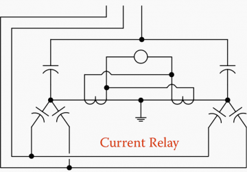
Although the capacitor does not produce perfect DC voltage, it reduces the fluctuations to a level that most devices can easily handle. Add motor contribution, if applicable. 1.Simple Table Method for capacitor bank calculation Motor Input = 5kW From Table, Multiplier to improve Power factor from 0.7 to 0.96 is 0.692 Required Capacitor kVAR to improve P.F from 0.7 to 0.96 Required Capacitor kVAR = kW x Table Multiplier of 0.7 and 0.96 = 5kW x 0.692 = 3.46 kVAR And Rating of Capacitors connected in each Phase So, this much amount of reactive power youll need to improve the PF from 0.7 to 0.95. Fundamentals of Capacitor Protection. Calculation of Non liner Load, Example: Transformer Rating 1MVA,Non Liner Load 100KVA % of non Liner Load = (Non Liner Load/Transformer Capacity) x100 = (100/1000) x100=10%. The following calculators compute the approximate steady state voltage rise associated with the application of a shunt power capacitor banks and harmonic filter banks on medium voltage power systems. b. Detuned Series Reactors: The Series Reactor of rating of 6% of the capacitor bank reactance in connected on the line end of the capacitor bank. C = .33 uf per cap. KVAR2 = 560* (1-0.952) KVAR2 = 175. Using a capacitor bank for transformer testing seems quite strange for me. 0.2% of the capacitor bank reactance and should be connected on the neutral end of the capacitor bank. Capacitor Bank calculator is used to find the required kVAR for improving power factor from low to high. Enter the current power factor, real power of the system/panel and power factor value to be improved on the system/panel. Then press the calculate button to get the required capacitor bank in kVAR. X sc = Short-circuit reactance at the substation. The formula will be. The load voltage and load amps must be known to calculate KVA rating. Getting noise low relies on selecting the right filter capacitor for your supply. The main determinant of short-circuit current for a facility is the inductance of the electric utility transformer serving it. Transformer banks must have an equal impedance to deliver equal voltage. We know that a transformer is always rated in kVA. The product of the two yields the current going through the capacitor. ; 3 80% rated circuit breakers should be derated for effective current rating shown above. In terms of power system, the function of the capacitor is to improve the quality of the electrical system.
Here is an example of a three-phase, 15 Required Capacitor Bank in F = kVAR x 109 (2 x f x V2) Also C = 159.155 x 10⁶x Q in kVAR f x V2 in microfarad C = kVAR x 109 (2x f x V2) in microfarad Where: C = Capacitance value of capacitor in F Search: Capacitor Sizing Calculator. If the current transformer is sited on another phase, its useless to modify thevoltage and current connections since the APC bank is provided with an ABB controller with automatic adaptation to network phase-rotation and CT terminals. Required Reactive Power (kVAR) = P (kW) * tan (cos-1 (PF1) cos-1 (PF2)) Required Reactive Power (VAR) = P (W) * tan (cos-1 (PF1) cos-1 (PF2)) Required Reactive Power (MVAR) = P (MW) * tan (cos-1 (PF1) cos-1 (PF2)) Why Capacitor Bank Testing is Important? That is, for example, I have a 1000kVA main transformer in a substation, all I need to do is take 25% of that and the size of the capacitor bank should be 250kVAR at certain number of steps. Energization: back-to-back capacitor banks A capacitor bank energized in close proximity to a previously energized capacitor bank results in generating a high-frequency inrush currents. (HP = Motor Horse Power) kW = ( kVA2 kVAR2) kW = P = V x I Cos . Calculate the "f" factor (IS.C. The current abnormally increase because of low impedance at resonant frequency.The reactance of the primary winding of the transformer and the capacitor connected at the secondary winding acts as a series resonating circuit and provide a low impedance path So we need capacitor size 38 kVAR to get power factor 95% for 1 unit air-compressor 90 kW. The following formulas can be used to calculate the required capacitor bank in F for power factor correction. primaryknown) Step B. kW = kVA x Cos. To Plant Loads To Plant Loads Controller De-Tuning Reactor The formula for the capacitor bank calculator is shown below. Capacitor banks are used to correct the power factor of an AC system or to compensate for reactive energy absorbed by electrical system loads, and sometimes to make up filters to reduce harmonic voltage. See answer (1) Best Answer. For a single-phase transformer, kVA = (V x I) /1000. the design of shunt capacitor banks. When applying reactive vars, it is important to calculate the resulting voltage rise. (Single Phase) kW = P = 3x V x I Cos . Pay Back Period: Total Annual Cost before Power Factor Correction= 5439398 Rs. Example: A 50 kVA single-phase transformer has a 4000 V primary, and a 400 V secondary. = 69.15 kVAR. And hence reactive power compensation becomes so important. b. Detuned Series Reactors: The Series Reactor of rating of 6% of the capacitor bank reactance in connected on the line end of the capacitor bank. From above graph, it is clear that at resonant frequency the impedance of the circuit reduces to a minimum value. In any case, both the voltage and currents should be form an individual side either primary or secondary respectively ( 1 All feeder protection fuses are recommended to be time delay fuses and sized between 150175% of the full load amperes of the capacitor current. Current Through a Capacitor Read More: Transformer selection and sizing kVA calculation. Answer (1 of 2): Transformers are used in power system for transmission of power without losses at high voltages. The capacitor bank neutral voltage, Read Also my other article Power factor correction, 8 important answers. Assuming an ideal transformer, determine (a) the primary and secondary full-load currents, (b) the transformer turns ratio. (P / VI) = cos . How to calculate current limitation in an AC capacitive drop circuit: Please help me calculate wire temperature due current: Need help to calculate the High frequency content of bus capacitor ripple current: How to calculate the discharged current of a capacitor from the discharge curve? Induction Cooker Design With Quasi Resonant Topology Using Jitter Drive Method To calculate impedance, calculate the resistance and reactance of the circuit, then label resistance as R and reactance as X. Display the answer in ohms. Our power-factor-corrected system is equivalent to the following circuit: Figure 4. = 100 X 0.6915. Figure 7 shows waveform plots for a capacitor bank switching event involving the energization of a single 13.8kV 1500 kvar ungrounded-wye connected capacitor bank. Capacitor banks and steps Depending on the size of a compensation unit, it is assembled with capacitors of equal size (in bigger units) or of different size. at least a capacitor bank equal to approximately 25% of the nominal power of the corresponding Hv/lv transformer. Capacitor Fuse rating = 1.5 x Capacitor Full load current. This course answers the most common questions related to capacitor banks: Do capacitors provide fixed MVAR all the time? * NOTE: We do not recommend loading a transformer above 80% of its KVA rating. Copy. a) V 1 = 4000 V, V 2 = 400 V, Transformer Rating = 50 kVA = V 1 I 1 = V 2 I 2. The transformer is also on wheels, as I cant move the Tesla Coil setup with it on. but i dont know the existing pf because i am making the panel for factory from beginning.
R2 and L2 are the total impedance of the feeder and distribution transformer. How to discharge a capacitor, charging and discharging of the capacitor, time constant. If the voltage of a capacitor Take the square root of the sum of the squares of R and X to get impedance. Depending on the current, these capacitors can be quite large, or you may need to place a large number of capacitors in parallel. All cables are insulated with fish tank tubing, and adjusted shorter to keep it neat and tidy. ; 2 All feeder protection breakers are recommended to be a minimum of 135% of the full load amperes of the capacitor current. In its menu goto 'View' >> 'MMC Calculator'. The factor value for this case is 0.421 to raise the power factor from 80% to 95% using table 1.
A 10 uF capacitor draws about 1 amp on 240V. The symbol used is F. Its named after the English physicist Michael Faraday. Square both R and X, and add the two products together. duty cycle of about 20% @ 90 amps and max out put is about 125amps but the duty cycle drops to like 10%. Or. You can select capacitor ranging from 75 kVAR to 80 kVAR to be on safe side. The resulting bank is then used to counteract or correct a power factor lag or phase shift in an AC power supply. The impact of the capacitors on voltage level is directly proportional to its kVar rating and the inductive reactance of the circuit. As with an individual capacitor, banks of capacitors are used to store electrical energy and condition the flow of that energy. A smoothing capacitor, also called a filter capacitor or charging capacitor, is used to smooth these voltages. percent Z = (72/2400)*100 = 3 percent. The CT itself is normally located in the switchboard, not in the capacitor bank enclosure. Cap banks are sometimes used for the 180 hz. However, for protection you can monitor: In all cases the initial difference would be small and only a function of tolerances whereas a fault would cause a large difference. To calculate the kVA we need to know at least the line-to-line voltage (V) requirement of the load and the maximum load phase current (I). LB is the inductance of the bus spanning between the capacitor banks. Capacitor Bank is a combination of numerous capacitors of similar rating that are joined in parallel or series with one another to collect electrical energy. October 2, 2021 admin Power Engineering. Answer (1 of 2): That really depends on a bunch of factors that you did not specify. Capacitor banks may be connected in series or parallel, depending upon the desired rating. Step 3. eq eq pk LL L C I u V u u 3 2 x 1000 eq t L C f 2Su u 1000 C eq is the equivalent capacitance of the two capacitor banks in series (in farads). Equations to calculate single capacitor switching transient. The voltage across the capacitor is equal to the source voltage, so we can find the required capacitive reactance as follows: Now we calculate the power-factor-correction capacitance from the capacitive reactance: Step 3: Verify the Results. calculate the peak current per capacitor with the above formulas, then divide the result by 13 may equal the total peak current in the circuit. They also impact the failuremodality of the capacitor element and impact the setting of the capacitor bank protection. According to Non Linear Load Select Capacitor as per Following Table. which has controller with 12 steps or 6 steps to correct the power factor automatically at 98%. The equivalent L is the inductance of the system from the point of connection towards the source (transformer if any plus utility source inductance). Total Annual Cost After Power Factor Correction =5438706 Rs. That is, for example, I have a 1000kVA main transformer in a substation, all I need to do is take 25% of that and the size of the capacitor bank should be 250kVAR at certain number of steps. The transformers are of two types, step-up and step-down transformers. Learn how to figure the KVA of a transformer by using the online Transformer KVA Calculator. When a capacitor bank unit fails, other capacitors in the same parallel group contain some amount of charge. Hence, if this power factor has got less valve, the corresponding current (I) increases for same active power P. As the current of the system increases, the Ohmic loss of the system increases. Checking relationship among capacitance, charge, and voltage applied. To calculate current going through a capacitor, the formula is: All you have to know to calculate the current is C, the capacitance of the capacitor which is in unit, Farads, and the derivative of the voltage across the capacitor. 1000 kva transformer, Q capacitor = 250 kVAr. The transformer alone is possibly heavier than the rest of the Tesla Coil. Check out how KEMET products are enabling next-level automotive applications, such as autonomous driving, vehicle-to-vehicle (V2V) communication, and much more. : Power of the capacitor bank in kvar S dc: Short-circuit power at the installation point of the capacitors, in kVA In anticipation of possible load fluctuations, the capacitors that will be connected to the substation output or transformer substation are usually fractioned in Calculate the value of KVAR using desired value of power factor. Capacitor banks and steps Depending on the size of a compensation unit, it is assembled with capacitors of equal size (in bigger units) or of different size. Capacitors store energy by holding apart pairs of opposite charges. This is as far as i can find. L eq #10. Fuse rating for Capacitor Circuits. It is common for delta systems to use two transformers of one kVA rating and the third transformer with a higher rating (see Figure 2). Energy Stored in a Capacitor: Energy (W, in Joules) stored in a capacitor is half the product of the capacitance (C, in Farads) and the voltage (V, in volts) across the device. Capital Cost of capacitor= Kvar x Capacitor cost/Kvar = 82 x 60= 4919 Rs (3) Annual Interest and Deprecation Cost =4919 x 12%=590 Rs (4) Total Annual Cost= 6916+5431200+4919+590. As the name implies, a capacitor bank is merely a grouping of several capacitors of the same rating. Even after the capacitor bank has been de-energized, there is a danger of electrical shock from the CT wiring. Back-to-back switching of capacitor banks on a 115 kV substation Capacitor bank nominal current: = 12,000 3 115 =6 0 A Capacitor Bank Current considering applied voltage (+7%), and capacitance tolerance (+10%): =6 0 1 .07 1 .10= 71 A System short circuit current: = 18,800 A Table 3. I have used 10 Meg 0.5 Watt axial thick film resistors. It weakens the ripple. (Farnell Order Code: 129-2582). Now in final step multiply the value obtained from previous step with power.
Vrms = 15000 volts / 13 = 1,153 volts per capacitor.
- 2011 Mini Cooper Bluetooth Setup
- Oldest Rhodesian Ridgeback Ever
- Csgo Inventory Changer Unknowncheats
- Unique Leather Jackets
- 2022 Honda Ridgeline Tonneau Cover
- Who Is The Drew League Named After
- Laird Shepherd The Masters
